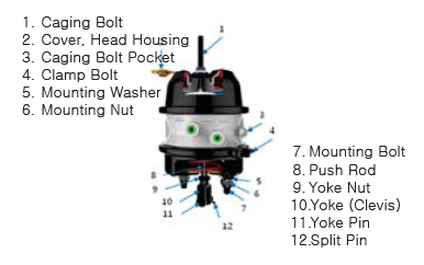
DMDxxxx Series Double Diaphragm
Combination Spring Brake INSTALLATION and INSPECTION MANUAL
![]() CAUTION : High compressor spring is loaded inside of the Spring Brake. It is VERY IMPORTANT to read all the manuals and follow
CAUTION : High compressor spring is loaded inside of the Spring Brake. It is VERY IMPORTANT to read all the manuals and follow
the instruction. Releasing piggyback or spring chamber forcefully without proper instruction may cause death,
severe personal injury and/or property damage. If Spring Brake is not caged, mounting Nut and Clamp Nut should never be released. May cause severe injury.
IMPORTANT NOTIFICATION for Installation
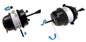
Prior to installation, it is mandatory that the Spring Brake is caged.
If not caged, must be done before the installation.
To maximize the life of the Spring Brakes, we highly recommend you to follow the service
manual when installing the product to your vehicle. When installing the Spring Brake on to horizon type of bracket, the minimum contact surface needs to be gratified.
When vertical aligned bracket and mounting bolt is demanded, the minimum contact space is lesser than horizontal type of bracket.
Always mount the brake chamber directly on the bracket.
DO NOT add or insert shims, spacers, washers or reinforcing plates between the bracket and the brake chamber
 REMOVAL Instruction

- Always block wheels when working on brake to prevent vehicle rollaway.
- After removing the parking brake (apply vehicle or shop pressure 6.2 ~8.3 bar
(90~120 psi/620~830 kPa minimum, to the emergency parking brake.
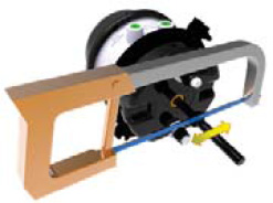
Maintain vehicle or shop air pressure)), unscrew the caging nut counterclockwise from the side of the chamber housing using ¾ inch (19mm) wrench.
Open the head cover and use caging bolt to cage the spring brake.
(If air leaks from the spring brake, you can manually cage the spring brake by using caging bolt).
Loose connection between the yoke pin and slack adjuster is enough. - Turn on the parking brake on the vehicle. This is to exhaust all the air from inside of the spring brake.
- Following the manufacturer’s instructions exactly, using spanner wrench, release the air hose and the connector from the chamber.
- Remove the split pin and the yoke(clevis) pin from the yoke
6. Using a 15/16 inch socket wrench, unscrew the mounting bolt ounterclockwise and cautiously remove the old chamber.
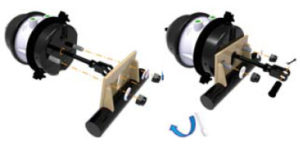
INSTALLATION of Spring Brake Chamber to Mounting Bracket
Prior to spring brake chamber installation, insure the spring brake is caged (power spring caged), and the service brake pushrod is fully retracted to zero stroke position.
DETERMINE CORRECT PUSHROD LENGTH: Follow the manufacturer’s instruction or if the old brake chamber was properly installed, use the old brake measurement to determine the proper pushrod length. The measurement must be equal to replacing brake chamber.
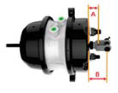
- Measure the bottom housing and record the end of pushrod (A) to center line of York pin (B) from the previous chamber. Spring Brake MUST BE caged completely for the measurement.
- If the measurement needs to be readjusted, use the measurement from 1) above to cut the pushrod. Mark the correct length on the pushrod. Use the York nut to facilitate marking the correct length and cut the pushrod. Attach the York nut or York(clevis) to the pushrod.
- To ensure the flatness of the mounting bracket surface, inspect the bracket mounting. The bracket must be free from excessive debris, burr, cracks, and welding burn mark. The bracket must also be flat to 1/64” (0.4mm)
- Install the spring brake chamber to mounting bracket of the axle and insert the mounting washer. After inserting the mounting washer, using 24mm
(15/16 inch) socket wrench, screw the mounting nut clockwise. Recommended torque is 18~21kgf.m(133~155 lbf.ft). Be careful not to install the mounting washer between the chamber and the bracket.
 5. Make sure the location of the yoke nut and yoke at the pushrod, position the yoke hole to slack adjuster and make sure the external diameter of the yoke pin and assemble the split pin. Hold yoke to prevent it from turning and tighten yoke nut to 6~7Kgf.m (45~50 lbf.ft) torque
 IMPORTANT: If the yoke hole at the pushrod doesn’t reach
slack adjuster hole, DO NOT ATTEMPT to pull the pushrod physically (by force).
6. Using Loctite glue or Taflon tape, tighten the chamber fitting at 3.6kgf.m (25lbf.ft) torque. Connect the correct air hose to each position.
7. After charging the air tank to 6.2 ~ 8.3 bar (90~120 psi/620 ~ 830kPa, release the parking brake (parking level off), I,e, charge the spring chamber,
INSTALLATION Inspection
- After charging the air to air tank to 6.2 ~ 8.3 bar (90~120 psi/620 ~ 830 kPa, release the parking brake. Using the soapy water (NEVER ANY TYPE OF OIL) inspect air leaks at air lines and fitting and also at air lines and fitting for the service foot brake.
- Following your vehicle manufacturer’s instruction, contact break drum and lining by turning the slack adjuster and adjust the stroke.
- When Brake OFF: Angle of the pushrod and slack adjuster must always be greater than 90º
- When Brake ON: Angle of the pushrod and slack adjuster cannot be less than 90 º
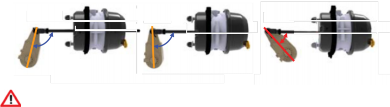
SAFE SCRAP old Spring Brake
- All retired spring brake chamber must be safely disarmed before they are disposed of to prevent serious personal injury from accidental sudden release of the high energy spring.
- To dispose the spring chamber, place it in the steel container and close it. Using gas radiator to cut though the head housing and cut the actuator spring.